Our OFDM implementation is based on the script from the lecture Digital signal processing, which was taught at the University of Applied Sciences Hagenberg by
FH-Prof. Dr.-Ing. habil. Hans-Georg Brachtendorf. The block diagram for the OFDM transmitter described in the script looks as follows:

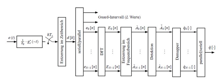
The Receiver block diagram looks as follows:

Transmission sequence generation

This Part of the Flowgraph will create the Sequence that will be transmitted through OFDM. Using the Chunks to Symbols Block and the Selector it is possible to choose between BPSK and QPSK modulation.
OFDM transmitter

The first block is the carrier allocator (gr::digital::ofdm_carrier_allocator_cvc). This sorts the incoming complex scalars onto OFDM carriers, and also places the pilot symbols onto the correct positions. There is also the option to pass OFDM symbols which are prepended in front of every frame (i.e. preamble symbols). These can be used for detection, synchronisation and channel estimation. With this block we select the bands that we wish to use and the synchonisation words are added aswell. FFT length = 64 means that we have 64 Bands. The occupied carriers are the bands that we have selected. In our implementation we have selected 48 bands as occupied carriers. 4 additional bands are used for pilot symbols. The other bands including the band at the index 0 are not used.
Carriers are always index starting at the DC carrier, which has the index 0 (you usually don’t want to occupy this carrier). The carriers right of the DC carrier (the ones at higher frequencies) are indexed with 1 through N/2-1 (N being the FFT length again). The carriers left of the DC carrier (with lower frequencies) can be indexed -N/2 through -1 or N/2 through N-1. Carrier indices N-1 and -1 are thus equivalent. The advantage of using negative carrier indices is that the FFT length can be changed without changing the carrier indexing.
The carrier allocator outputs OFDM symbols (i.e. complex vectors of FFT length). These must be converted to time domain signals before continuing, which is why they are piped into an (I)FFT block. Note that because all the OFDM symbols are treated in the shifted form, the IFFT block must be shifting as well.
Finally, the cyclic prefix is added to the OFDM symbols. The gr::digital::ofdm_cyclic_prefixer can also perform pulse shaping on the OFDM symbols (raised cosine flanks in the time domain).
FFT shifting
In all cases where OFDM symbols are passed between blocks, the default behaviour is to FFT-Shift these symbols, i.e. that the DC carrier is in the middle (to be precise, it is on carrier floor(N/2) where N is the FFT length and carrier indexing starts at 0).
The reason for this convention is that some blocks require FFT-shifted ordering of the symbols to function (such as gr::digital::ofdm_chanest_vcvc), and for consistency’s sake, this was chosen as a default for all blocks that pass OFDM symbols. Also, when viewing OFDM symbols, FFT-shifted symbols are in their natural order, i.e. as they appear in the pass band.
Channel

The above image shows the channel simulation. By using the noise source block we can simulate white gaussian noise.
Synchronization

The above flowgraph is the handles the synchronization for our ofdm transmission. The first block is a Schmidl & Cox synchronization block. Schmidl and Cox propose a synchronization algorithm that bases on an OFDM symbol that has a special structure. In particular, the special symbol, denoted as the preamble, consists of two repeated parts, prepended by a cyclic prefix (CP).

Each frame starts with a preamble which consists of two repeated parts, denoted by A. Subsequently, there will be N OFDM symbols following containing the payload information. In the Schmidl and Cox proposal, the preamble can also contain information, as the part A can be arbitrary. The only criterion is that the part is repeated twice.
OFDM receiver

